SMD Assembly
1. Processes and Equipment
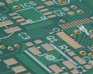
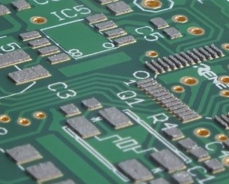
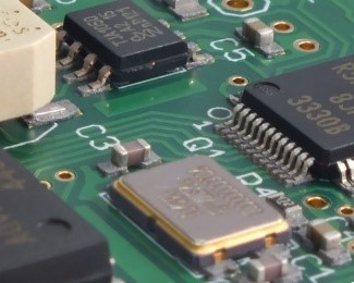
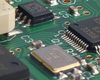
- BGA, Fine-pitch, 0402, 0201 components
- Placement capacity: up to 100,000 components/hour (3,500 fine-pitch)
- Reflow soldering / convectional
- RoHS-compliant manufacturing
- Automatic and manual SMD placement (prototypes and small series)
- Exotic component handling
2. SMD Assembly Process Chain
SMD components are soldered using the reflow soldering process. This method involves heating the solder paste until it melts and forms permanent joints between components and PCB pads.
- Solder paste printing
- SMD component placement
- Reflow soldering
Step 1: Paste Printing
Step 2: Placement
Step 3: Reflow Soldering
Step 4: AOI Inspection
3. Solder Paste and Printing
A stencil is prepared (typically 100 µm or 150 µm thick). During the solder paste printing process, the paste is applied through the stencil using a squeegee. The printer ensures parallel lifting of the PCB to maintain consistent paste volume and shape.
A perfect solder paste print is one of the most critical quality factors in SMD manufacturing. Both leaded and lead-free solder pastes can be used, but we recommend lead-free (RoHS-compliant) to avoid issues with mixed metallization.
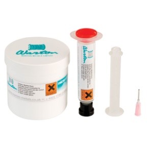
Example Solder Paste:
- Manufacturer: Warton Metals
- Type: Microprint P2010
- Alloy: SAC305 88.0 25–45
- Flux: No-Clean
- Standard: IPC 650 compliant
4. Component Placement
After printing, components are placed on the solder paste, which acts as an adhesive. Placement is performed by automated pick-and-place machines. For prototypes and small batches, manual placement is used, ensuring the same quality as series production.
5. Reflow Soldering
Once placed, the PCB passes through the reflow oven. We use two convectional reflow ovens with conveyor systems. The entire assembly follows a defined temperature profile. The solder paste melts into solder and permanently connects the components to the PCB pads.
A common misconception is that accurate placement ensures accurate alignment after soldering. During reflow, components float briefly on molten solder and self-align due to surface tension. The pad design and quality of solder paste printing are critical to prevent misalignment. Approximately 50% of soldering defects originate from stencil printing.
6. Production Lines
Line 1 (15,000–25,000 components/hour)
- Printer: Europlacer EP700
- Handling system
- Placement machine: iineo+
- Reflow oven: SMT-Wertheim
- AOI system: Marantz
Line 2 (15,000–25,000 components/hour)
- Printer: Europlacer EP700
- Handling system
- Placement machine: iineo+
- Reflow oven: SMT-Wertheim
- AOI system: Marantz
Line 3 (3,000 components/hour)
- Printer: DEK 248
- Placement machine: Juki 570
- Reflow oven: SMT-Wertheim
- AOI system: Quins
Line 4 (3,000 components/hour)
- Printer: DEK 248
- Placement machine: Juki 570
- Reflow oven: SMT-Wertheim
- AOI system: Quins
Our Europlacer placement machines can be equipped with up to 160 standard feeders and 20 additional trays for BGAs. Components from 0201 packages up to BGAs with 0.4 mm pitch can be processed. Individual components unsuitable for automatic feeding are manually placed.
7. Prototype and Sample Production
In certain cases, especially for non-recurring or small-quantity assemblies, manual placement is more economical. When complexity and quantity are low, programming and setup for automated lines may not be justified. Manual assembly ensures flexibility without compromising quality.