data/files
data provision
In addition to the data for the production of the printed circuit board, we also need further information.
It form the basis so that the project can be processed quickly and easily.
Along with conventionally provided data, we also work directly with the information from your CAD projects like Eagle
(*.sch + *.brd), Protel (*.ddb), Altium Designer (*.pcbdoc), Target3001 (*.T3001) oder ODB++.
All relevant data is available in the files of the common layout programs and can be processed by us without any problems.
If you do not have any board data, we need at least that the following information:
- Assembly print/assembly plan (readable) in PDF format or from board and Gerber data
- Parts list
- Pick&Place file
- Gerber data to create the solder paste stencil for the present panel
Parts list/Bill of Materials
The quality of the parts list determines how quickly an offer can be created or an order processed.
In particular, the clear description of all components also helps to minimize the risk of technical errors.
Inaccurate parts lists with little detailed information require a lot of clarification.
The parts list should be available as an Excel file or – at least – in a convertible format.
The customer parts list should contain the following essential information:
- Position number
- Component name or designator (e.g. R1, C1, D1, IC1, etc.)
- Type/Value (e.g. 1k1, 47nF, 1N4005G, MAX232ACWE+ , etc.
- Case (e.g. 0603, 1206, Elko SMD-C, etc.)
- Is assembled: yes/no
- Number of pieces, quantity per item
- Provided by customer: yes/no
- assembly instructions
- Distributor and its part number
| Pos. | Part | Description | Value | Place | Manufacturer | PartName | Quantity | Provided by | Link |
|---|---|---|---|---|---|---|---|---|---|
| 1. | C1, C2 | POLARIZED CAPACITOR | 470uF | No, Yes | - | CPOL-EUE5-8.5 | 1 | ProfiAnts | www. .. |
| 2. | D1, D2 | Z DIODE | BZV55C10SMD | Yes, Yes | - | BZV55C10 SMD | 2 | ProfiAnts | www. .. |
| 3. | Q1, Q2, Q3 | PNP SOT223 transistor 1,0A,60V | BZV55C10SMD | Yes, Yes, No | - | BCP55-16 SMD | 2 | by customer | www. .. |
| 4. | R1, R2, R3, R4 | Resistor 47k | BZV55C10SMD | Yes, Yes, No, Yes | - | R-EU_M0805 | 3 | ProfiAnts | www. .. |
| 5. | X1, X2, X3 | PHOENIX miniature 2,54 | - | Yes, Yes, No | PHOENIX CONTACT | MPT 0,5/ 2-2,54 | 2 | ProfiAnts | www. .. |
| Number of components to be assembled: | 10 | ||||||||
remark:
Please remove non-electrical elements such as screws, nuts, washers, distance bolts, labels, test points from the list if they are not to be assembled.
Pick&Place file
Pick&Place file is required to ensure error-free placement of components.
The parts list should be available as an Excel file or – at least – in a convertible format.
The customer parts list should contain the following essential information:
- Reference name / component name
- Case
- Electrical value
- X and Y position of the components relative to the layout zero point (component center)
- angle of rotation
- In Case of double side assembly - Info for TOP or BOTTOM placement
Example for Pick&Place file:
| Pos. | Part | Description | Value | Place | Side | X,mm | Y,mm | Rotate, ⁰ |
|---|---|---|---|---|---|---|---|---|
| 1. | C1 | POLARIZED CAPACITOR | 470uF | No | TOP | 20,32 | 7,62 | 270 |
| 2. | C2 | POLARIZED CAPACITOR | 470uF | Yes | TOP | 36,83 | 7,62 | 270 |
| 3. | D1 | Z DIODE | BZV55C10SMD | Yes | TOP | 12,7 | 8,89 | 270 |
| 4. | D2 | Z DIODE | BZV55C10SMD | Yes | TOP | 12,7 | 19,05 | 90 |
| 5. | Q1 | PNP SOT223 transistor 1,0A,60V | Yes | TOP | 19,05 | 22,86 | 0 | |
| 6. | Q2 | PNP SOT223 transistor 1,0A,60V | Yes | TOP | 25,4 | 17,78 | 0 | |
| 7. | Q3 | PNP SOT223 transistor 1,0A,60V | No | TOP | 39,37 | 22,86 | 0 | |
| 8. | R1 | Resistor | 47k | Yes | TOP | 39,37 | 15,24 | 0 |
| 9. | R2 | Resistor | 47k | Yes | TOP | 33,02 | 22,86 | 270 |
| 10. | R3 | Resistor | 47k | No | TOP | 33,02 | 15,24 | 270 |
| 11. | R4 | Resistor | 47k | Yes | TOP | 19,05 | 17,78 | 270 |
| 12. | X1 | PHOENIX miniature 2,54 | Yes | TOP | 6,35 | 13,97 | 90 | |
| 13. | X2 | PHOENIX miniature 2,54 | Yes | TOP | 48,26 | 10,16 | 270 | |
| 14. | X3 | PHOENIX miniature 2,54 | No | TOP | 49,26 | 21,59 | 270 |
assembly plan
the plan should include the following information:
- component name
- value
- polarity mark
- assembly drawing
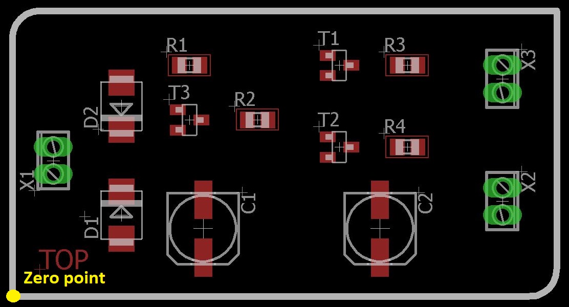
- Position of the layout zero point, if possible marked in the silkscreen
- All values and reference designations of the components should be clearly marked
Attention: There is often no clear information for the correct rotation of components with reverse polarity,
including sockets and plugs, in the assembly plan or in the identification print.
This leads to considerable inquiries and increases the risk of errors in the assembly.
Solder Paste Stencil
We will generate the data for the stencil production from your CAD data
or enclose Gerber data for the creation of the solder paste template in your project.
All pads that should not receive solder paste should be marked.